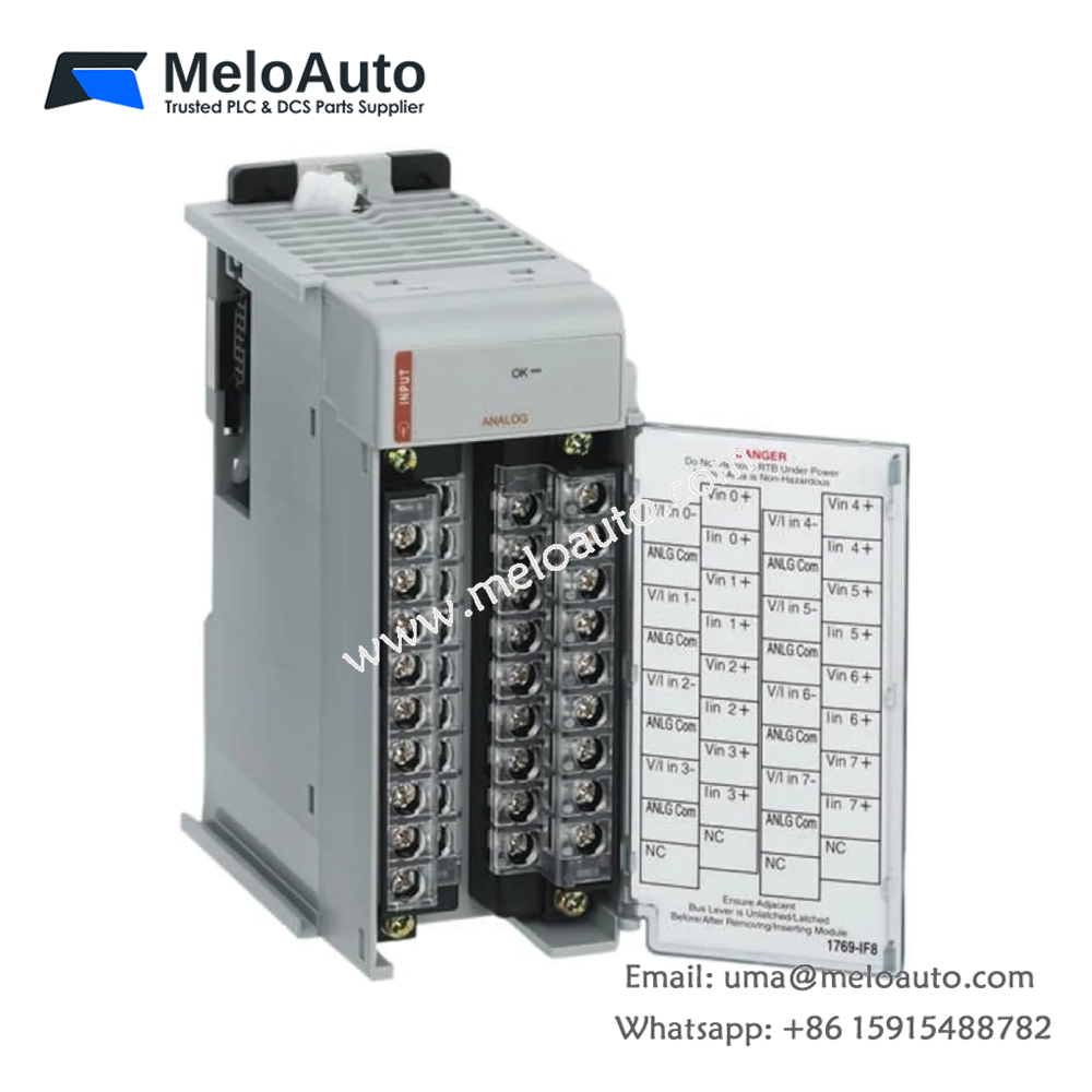
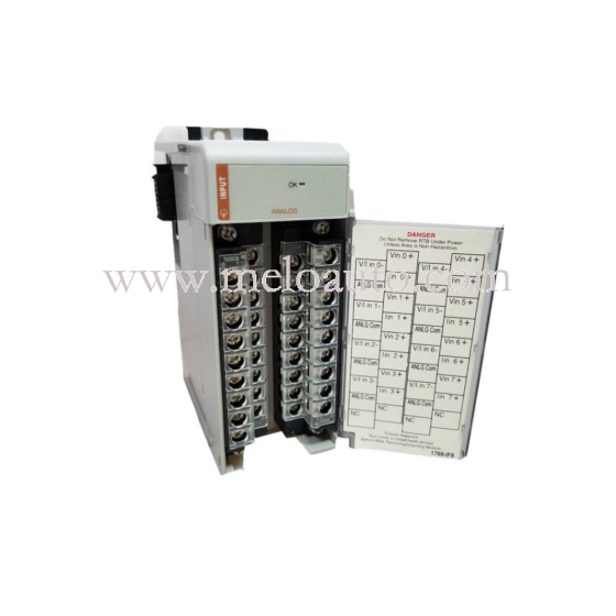
The Allen-Bradley 1769-IF8 is a Compact I/O analog input module with Eight (8) input channels. This module is designed to interface field devices that sends 0-21 mA and +/- 10VDC analog signals. This module is compatible for use with a 1769 CompactLogix chassis or MicroLogix 1500 controller.
Specifications
General Specifications
| Specification | Value |
|---|---|
| Dimensions | 118 mm (height) x 87 mm (depth) x 52.5 mm (width) height including mounting tabs is 138 mm |
| 4.65 in. (height) x 3.43 in (depth) x 2.07 in (width) height including mounting tabs is 5.43 in. | |
| Approximate Shipping Weight | 450g (0.99 lbs.) |
| Storage Temperature | -40°C to +85°C (-40°F to +185°F) |
| Operating Temperature | 0°C to +60°C (32°F to +140°F) |
| Operating Humidity | 5% to 95% non-condensing |
| Operating Altitude | 2000 meters (6561 feet) |
| Vibration | Operating: 10 to 500 Hz, 5G, 0.030 in. peak-to-peak |
| Shock | Operating: 30G, 11 ms panel mounted (20G, 11 ms DIN rail mounted) |
| Non-Operating: 40G panel mounted (30G DIN rail mounted) | |
| Agency Certification | C-UL certified (under CSA C22.2 No. 142) UL 508 listed, CE compliant for all applicable directives |
| Hazardous Environment Class | Class I, Division 2, Hazardous Location, Groups A, B, C, D (UL 1604, C-UL under CSA C22.2 No. 213) |
| Radiated and Conducted Emissions | EN50081-2 Class A |
| Electrical/EMC | ESD Immunity (IEC1000-4-2): 4 kV contact, 8 kV air, 4 kV indirect |
| Radiated Immunity (IEC1000-4-3): 10 V/m, 80 to 1000 MHz, 80% amplitude modulation, +900 MHz keyed carrier | |
| Fast Transient Burst (IEC1000-4-4): 2 kV, 5kHz | |
| Surge Immunity (IEC1000-4-5): 1 kV galvanic gun | |
| Conducted Immunity (IEC1000-4-6): 10 V, 0.15 to 80 MHz(1) | |
| Notes | (1) Conducted Immunity frequency range may be 150 kHz to 30 MHz if the Radiated Immunity frequency range is 30 MHz to 1000 MHz. |
Input Specifications
| Specification | Value |
|---|---|
| Analog Normal Operating Ranges | Voltage: ±10V dc, 0 to 10V dc, 0 to 5V dc, 1 to 5V dc Current: 0 to 20 mA, 4 to 20 mA |
| Full Scale Analog Ranges | Voltage: ±10.5V dc, 0 to 10.5V dc, 0 to 5.25V dc, 0.5 to 5.25V dc Current: 0 to 21 mA, 3.2 to 21 mA |
| Number of Inputs | 8 differential or single-ended |
| Bus Current Draw (max.) | 120 mA at 5V dc, 70 mA at 24V dc |
| Heat Dissipation | 3.24 Total Watts |
| Converter Type | Delta Sigma |
| Response Speed per Channel | Input filter and configuration dependent. See your user’s manual. |
| Resolution (max.) | 16 bits (unipolar), 15 bits plus sign (bipolar) |
| Rated Working Voltage | 30V ac/30V dc |
| Common Mode Voltage Range | ±10V dc maximum per channel |
| Common Mode Rejection | Greater than 60 dB at 50 and 60 Hz with the 10 Hz filter selected |
| Normal Mode Rejection Ratio | -50 dB at 50 and 60 Hz with the 10 Hz filter selected |
| Input Impedance | Voltage Terminal: 220K Ω (typical) Current Terminal: 250 Ω |
| Overall Accuracy | Voltage Terminal: ±0.2% full scale at 25°C Current Terminal: ±0.35% full scale at 25°C |
| Accuracy Drift with Temperature | Voltage Terminal: ±0.003% per °C Current Terminal: ±0.0045% per °C |
| Calibration | The module performs autocalibration on channel enable and on configuration changes between channels |
| Non-linearity (in percent full scale) | ±0.03% |
| Repeatability | ±0.03% |
| Module Error over Full Temperature Range (0 to +60°C) | Voltage: ±0.3% Current: ±0.5% |
| Input Channel Configuration | Via configuration software or user program (by writing a unique bit pattern into the module’s configuration file). |
| Module OK LED | On: Power, passed diagnostics, communicating over the bus Off: Failure in any of the above |
| Channel Diagnostics | Over- or under-range by bit reporting, process alarms |
| Maximum Overload at Input Terminals | Voltage Terminal: ±3.0V dc continuous, 0.1 mA Current Terminal: ±32 mA continuous, ±7.6 V dc |
| System Power Supply Distance Rating | The module may not be more than 8 modules away from the system power supply |
| Recommended Cable | Belden™ 8761 (shielded) |
| Input Group to Bus Isolation | 500V ac or 710V dc for 1 minute (qualification test) 30V ac/30V dc working voltage (IEC Class 2 reinforced insulation) |
| Vendor I.D. Code | 1 |
| Product Type Code | 10 |
| Product Code | 38 |
Notes:
- The over- or under-range flag will indicate when the normal operating range is exceeded.
- Resolution depends on the filter selection.
- Rated working voltage is the maximum continuous voltage that can be applied at the input terminal.
- For proper operation, both the plus and minus input terminals must be within ±10V dc of analog common.
- Overall accuracy includes offset, gain, non-linearity, and repeatability error terms.
- Repeatability is the ability of the input module to register the same reading in successive measurements for the same input signal.
- Damage may occur to the input circuit if this value is exceeded.


-560x560.jpg "5SV3746-5")
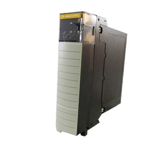


 Analog I/O Module")


WeChat
Scan the QR Code with wechat