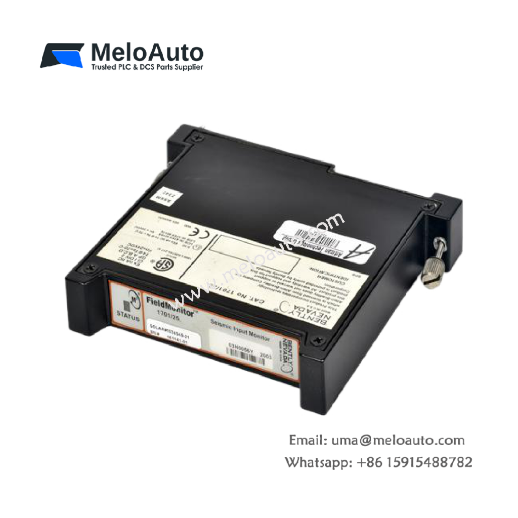
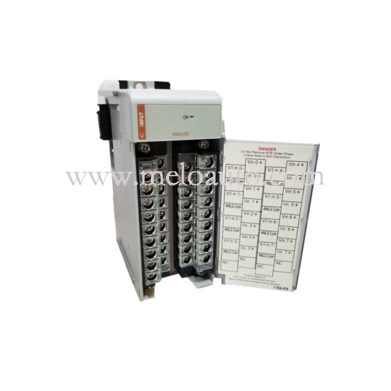
Description of the 1701/25 FieldMonitor™ Seismic Input Monitor
The 1701/25 FieldMonitor™ Seismic Input Monitor is a versatile 2-channel device designed to accept input signals from both acceleration and velocity transducers via its associated transducer I/O module. Once the signals are received, the device conditions them into the appropriate measurement units. It then compares the processed signals to user-programmable alarm setpoints, generating alarm signals when necessary for communication to the host control system.
Moreover, the monitor provides extensive signal processing capabilities, offering various filtering and integration functions. These capabilities ensure that the signals are appropriately conditioned before being processed. The monitor also provides real-time values of the measured parameters, which can be relayed to the control system for display and trend analysis. Additionally, embedded self-tests continuously monitor the integrity of both the device and its connected transducers. If an issue arises, a “Not OK” condition can be flagged to alert operators of potential problems.
Measurement Options
The 1701/25 Seismic Input Monitor can be configured to provide the following measurements:
- Direct velocity
- RMS velocity
- Integrated velocity
- Filtered direct velocity
- Filtered RMS velocity
- Filtered integrated velocity
- Direct acceleration
- RMS acceleration
- Filtered direct acceleration
- Filtered RMS acceleration
- Integrated direct acceleration (velocity)
- Integrated RMS acceleration
- Filtered integrated direct acceleration
- Filtered integrated RMS acceleration
It is important to note that velocity and acceleration transducers cannot be mixed in the same 2-channel monitor. Each channel can only provide one of the listed measurements, depending on the specific configuration chosen.
Specifications for Velocity Input (1701/25 Seismic Input Monitor)
Programmable Options (Proportional Values per Channel):
The monitor offers various programmable options to cater to different needs. These include direct velocity, RMS velocity, integrated velocity, filtered direct velocity, filtered RMS velocity, and filtered integrated velocity.
Alarms and Delay Options:
The monitor supports multiple alarm configurations, including Alarm 1 (Alert) and Alarm 2 (Danger), with user-defined time delays (ranging from 0.15 to 20.0 seconds). It also supports non-latching alarms, as well as adjustable alarm hysteresis, which is 0.5% of full scale.
In addition to these alarm features, users can configure the alarm trip multiply factor, which can be set to None, 1.5, 2, or 3. Furthermore, the system allows timed OK channel defeat, offering flexibility in various operational conditions.
Signal Processing and Filtering:
The device comes equipped with comprehensive signal processing options, including bandwidth filtering. For example, direct velocity measurements can be filtered from 3 Hz to 5,500 Hz, with customizable low-pass (LP) and high-pass (HP) filters available. The programmable corner frequencies for these filters range from 3 Hz to 120 Hz for high-pass filters and from 5500 Hz to 100 Hz for low-pass filters.
Full-Scale Velocity Ranges:
The monitor supports a variety of full-scale ranges for both peak and RMS velocity measurements, ensuring that it can be adapted to different applications. Some of these ranges include:
- Peak velocity: 0 – 0.5 in/s, 0 – 1.0 in/s, 0 – 2.0 in/s, and more.
- Integrated velocity (pp): 0 – 5 mil, 0 – 10 mil, 0 – 20 mil, and more.
- RMS velocity: 0 – 0.5 in/s rms, 0 – 1.0 in/s rms, 0 – 2.0 in/s rms, and more.
Specifications for Acceleration Input (1701/25 Seismic Input Monitor)
Programmable Options (Proportional Values per Channel):
For acceleration input, the monitor provides the following programmable options: direct acceleration, RMS acceleration, filtered direct acceleration, filtered RMS acceleration, integrated direct acceleration (velocity), integrated RMS acceleration, filtered integrated direct acceleration, and filtered integrated RMS acceleration.
Alarms and Delay Options:
Similar to the velocity input, the acceleration input also features alarm configurations with user-defined time delays. These delays range from 0.15 to 20.0 seconds, and the system supports non-latching alarms. Adjustable alarm hysteresis of 0.5% of full scale is also included, along with trip multiply factors and timed OK channel defeat.
Signal Processing and Filtering for Acceleration:
The monitor offers a wide range of filter options, with the ability to adjust the high-pass and low-pass filter corner frequencies. For example, the dual-channel 14.05 kHz Acceleration Monitor offers high-pass corner frequencies from 3 Hz to 200 Hz and low-pass corner frequencies from 14050 Hz to 1100 Hz. These filtering options are critical in ensuring that the signal is accurately processed before being output.
Full-Scale Acceleration Ranges:
The monitor supports several full-scale ranges for both peak and RMS acceleration, ensuring it meets the needs of various industrial applications. These ranges include:
- Peak acceleration (no integration): 0 – 2 g’s pk, 0 – 5 g’s pk, 0 – 10 g’s pk, and more.
- Integrated acceleration (pk): 0 – 1.0 in/s pk, 0 – 2.0 in/s pk, and more.
- RMS acceleration: 0 – 2 g’s rms, 0 – 5 g’s rms, 0 – 10 g’s rms, and more.
Barriers:
The system includes internal galvanically isolated barriers, which require the 1701/06 Isolator Terminal Base. Additionally, external Zener and galvanically isolated barriers are also available for further protection.
Ordering Information
The FieldMonitor™ Seismic Input Monitor for Velocity and Acceleration Input is available under the model number 1701/25-01.


 Analog I/O Module")


WeChat
Scan the QR Code with wechat