


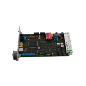
System Overview
System DOPS
- Certified according to SIL3 – DIN EN 61508.
- Requires:
- 3 x monitor MMS 6350 (/DP) (including firmware application no. 0)
- Optional Profibus interface.
System DOPS AS
- Designed for Astom applications, also certified to SIL3.
- Requires:
- 3 x monitor MMS 6350 (/DP) (including firmware application no. 2)
- Optional Profibus interface.
Technical Data
- Signal Input:
- Differential input, non-reactive, open-circuit and short-circuit proof.
- Input Voltage Range:
- 0…30 Vdc
- Input Resistance:
100 kOhm
- Sensor Signal Output:
- Front socket SENS, decoupled, open-circuit and short-circuit proof, non-reactive, not calibrated, in phase with sensor signal.
- Voltage Range: 0….4.1 Vpp
- Amplitude: Sensor signal x (-0.15)
- Accuracy: ±1% of full scale
- Frequency Range: 0…16 kHz (-3 dB) ±20%
- Permissible Load Resistance: > 1 MΩ
- Internal Resistance: 10 kOhm
- Dynamic Outputs:
- Front Socket Pulses: Processed input pulses output as TTL pulses, open-circuit and short-circuit proof, non-reactive.
- Nominal Range: TTL level, 5 VSS
- Frequency Range: 0 Hz…20 kHz
- Permissible Load Resistance: > 1 MΩ
- Internal Resistance: 5.1 kΩ
- Pulse Output:
- Pulse-C, Pulse-E: Processed input pulses output via potential-free opto-coupler outputs.
- Max. Voltage (DC7): +48 Vdc on collector
- Max. Current with C-E Conducting: Current limitation on 25 mA
- Signal Conditioning:
- Input signals standardized before processing. Characteristic value proportional to speed.
- Max. Measuring Range: Limited to 20 kHz by max. input signal frequency.
- Max. Speed: 65.535 rpm
- Max. Number of Teeth: 255 (with Nmax = 4700 rpm)
Current Outputs
- Current Output 1 (Iout1):
- 0/4….20 mA / 20….4/0 mA, electrically isolated.
- Measuring Error: ±0.1% of full scale, 16-bit resolution.
- Current Output (Iout2):
- (Not available for DOPS TS)
- 0/4….20 mA / 20….4/0 mA with reference to internal GND.
- Accuracy: ±0.1% of full scale, 16-bit resolution.
- Speed Zoom Function: Programmable for each current output.
Channel Supervision and Visualization
- Permanent signal check for speed sensors, comparing signal pulses and current output.
- Faults indicated by two green LEDs at monitor front.
- Output “Channel Clear”: Operating mode (open/closed circuit) freely selectable.
- Voltage Output:
- +24 VDC = High state
- 0 VDC = Low state
- Max. Current: 25 mA (current limitation)
Binary Inputs
- Electrically Separated from System Ground
- 24 V – Voltage Inputs:
- Signal Level: “Low”: 0….+3 V, “High”: +13….+32 V
- Max. Input Voltage: +/- 35 V
- Input Resistance: 6.8 kOhm
- External Blocking: Disable function/alarm outputs for service and maintenance.
- Reset Latch: To reset latched function and alarm outputs.
- Test Inputs: For testing monitoring functions with simulated test values.
- Limit Setting: Configurable limits with state visualization using yellow LED for function/alarm outputs.
Binary Outputs
- Six function outputs with separate function or limit settings, designed as 24V voltage outputs.
- Voltage Range Binary Outputs:
- Supply of binary outputs via backplane, electrically isolated.
- Supply Voltage Range: Uout “High” = +18….32 V, Uout “Low” = 0…+3.5 V
- Iout Max: 25 mA
- Relay Outputs Backplane:
- 2 out of 3 combinations of function outputs and Channel Clear.
- Umax: 48 VDC, 20 Vrms AC
- Imax: 4 AAC, DC
- Max. Cable Cross-Section at Screw Terminals: 1.5 mm²
Communication Interfaces
- RS 232: Front socket for laptop connection for configuration and visualization.
- RS 485: Bus interface for communication with external systems.
- SUB-D Plug on Front Plate: For PROFIBUS-DP connection (optional).
Sensor Supply
- Decoupled and Electrically Isolated: Open circuit and short-circuit proof.
- Supply Voltage: 26.75 VDC
- Max. Current: 38 mA
- Residual Ripple: < 20 mVSS (at nominal current 20 mA)
Module Supply
- Two redundant inputs, decoupled via diodes, for nominal +24V with common ground.
- Current Consumption: Max. 250mA per card (with display).
- Permissible Voltage Range: 18….32 VDC according to IEC 60654-2.
Mechanical Design
- Format: Euro-Format (100 x 160 mm) according to DIN 41 494.
- Width:
- With display: 14 TE (approx. 71 mm)
- Without display: 6 TE (approx. 30 mm)
- Connector: DIN 41 612, type F 48 M.
Order Information
- Order Number:
- MMS 6350/DP Speed measurement card with PROFIBUS DP: 9100 – 00065
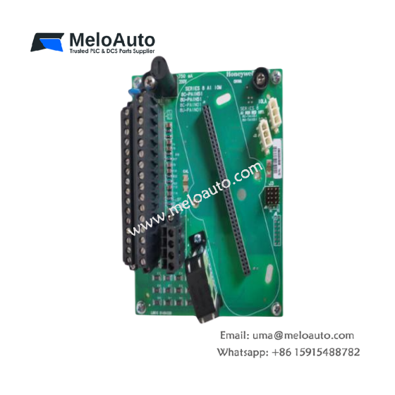


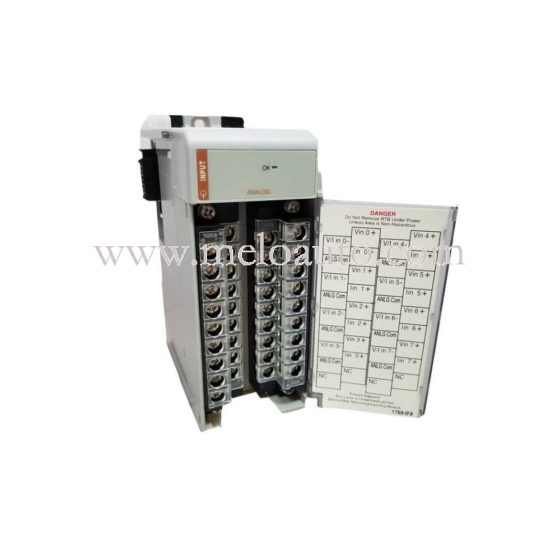
 Analog I/O Module")


WeChat
Scan the QR Code with wechat