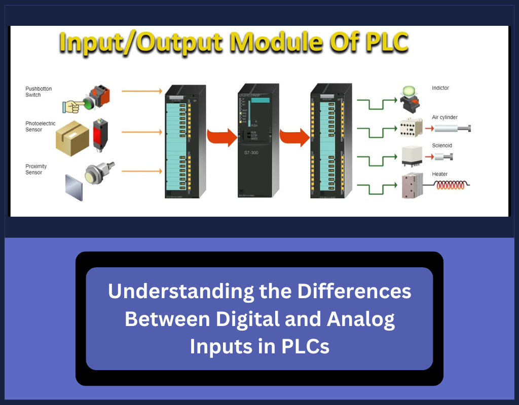
Programmable Logic Controllers (PLCs) are essential for industrial automation, providing efficient control and monitoring for complex processes. The input modules in PLC systems play a vital role in collecting data from field devices and sending it to the PLC’s CPU for processing. These inputs fall into two categories: digital and analog, each serving distinct functions. This article explores the differences between the two types of inputs, their applications, and how they contribute to automation systems.

Overview of PLC Inputs
PLCs bridge the gap between the physical world and the digital control environment. Input modules gather data from sensors and devices, process it based on programmed instructions, and provide output to control machinery or processes. These modules connect field devices to the PLC, ensuring accurate data collection and system functionality.
The two primary types of input modules are:
- Digital Inputs: Represent binary states—either ON or OFF.
- Analog Inputs: Handle continuous signals that capture a range of values.
Each type of input serves different purposes depending on the nature of the process being controlled.
Digital Inputs in PLCs
Digital inputs are the most common type in PLC systems. These inputs work with binary signals, which can be either HIGH (ON) or LOW (OFF). They come from devices that can only be in one of two states, such as push buttons, limit switches, or proximity sensors.
In a digital input system, the PLC detects whether a field device is active or inactive based on the voltage level. For example, if the input module operates at 24V DC, 0V represents an OFF state (binary 0), and 24V represents an ON state (binary 1). The PLC then uses this information to perform tasks like turning on motors or activating alarms.
Common Digital Input Devices:
- Push Buttons: Used for simple ON/OFF functions like starting or stopping equipment.
- Selector Switches: Allow operators to select between different modes or settings.
- Proximity Sensors: Detect objects without contact, often used for positioning in automation systems.
- Photoelectric Sensors: Use light to detect objects, ensuring precise positioning or counting.
- Limit Switches: Stop movement once a predetermined limit is reached, such as halting a conveyor belt.
Sourcing vs. Sinking in Digital Inputs
When setting up digital inputs, it’s essential to understand the concepts of sourcing and sinking. In sourcing (PNP), the device provides a positive voltage (e.g., +24V). In sinking (NPN), the device connects to the ground (e.g., -24V). This difference affects how the circuit is completed and how the PLC interprets the input signal.
Analog Inputs in PLCs
Analog inputs capture continuous signals that vary within a defined range, such as 0-10V or 4-20mA. These inputs provide the PLC with detailed information about conditions like temperature, pressure, or flow.
Analog inputs are essential when precise control and measurement are necessary. For example, a thermocouple may generate a voltage proportional to temperature, allowing the PLC to adjust heating elements or other equipment accordingly.
Common Analog Input Devices:
- Position/Displacement Sensors: Measure the movement or position of objects, such as linear potentiometers and rotary encoders.
- Thermocouples: Provide temperature measurements by generating voltage changes in response to heat.
- RTDs (Resistance Temperature Detectors): Offer precise temperature readings by changing resistance with temperature.
Key Differences Between Digital and Analog Inputs
Signal Type:
- Digital Inputs: Have two possible states—ON or OFF (binary).
- Analog Inputs: Offer a continuous range of values, providing more detailed real-world data.
Applications:
- Digital Inputs: Ideal for binary decisions, such as starting or stopping a motor.
- Analog Inputs: Used for precise control and monitoring, such as regulating temperature or pressure.
Complexity:
- Digital Inputs: Simpler to process, as they only involve two possible states, making them easier to troubleshoot.
- Analog Inputs: More complex due to the continuous signal range, but they provide greater accuracy and control.
Conclusion
Understanding the difference between digital and analog inputs is crucial for designing efficient PLC systems. Digital inputs are perfect for straightforward, binary tasks, while analog inputs offer detailed data for precise control. By choosing the appropriate input type for your application, you can optimize system performance and ensure reliable automation.
 MeloAuto-Trusted PLC & DCS Parts Supplier
WeChat
Scan the QR Code with wechat